Coming soon · RoboSim CAD Studio
You built the board.
The mechanical CAD isn't your job.
A CAD studio for electronics and robotics teams: upload a KiCad board, say what you need in plain language — the agent reads the outline, connectors, and mounting holes from the file and returns manufacturable, validated CAD. Enclosures first; mounts, brackets, panel cutouts, and test jigs are the roadmap.
The actual pipeline output — drag to inspect the real model, not a mockup.
Watch the full demo (90 seconds)
The whole flow — board file in, plain-language request, live pipeline run at 1× real time, validated files out.
UI shown is a product preview. Pipeline output, timings, and validation results are real.
How it works
1
Upload your board
.kicad_pcb in. The agent parses the outline (Edge.Cuts), the
connectors, and the mounting holes straight from the file.
2
Say it in plain language
"Dust-resistant case, demo units in three weeks." No screw specs, no cutout dimensions — the agent proposes them from the board and you confirm:
- ✓ 32.0 × 34.65 mm — outline from Edge.Cuts
- ✓ 2 edge connectors (JST-SH) → wall cutouts
- ✓ 4 mounting holes → screw bosses
- ✓ dust-resistant intent → lipped lid
3
Validated files out
STEP + STL + DXF + a signed PDF report: watertightness, wall thickness, board-fit interference, mass, and an analytic structural check — every part is checked before you see it.
Drawn to the numbers
The lid, drawn to the demo run's spec.json dimensions — board 32.0 × 34.65 mm, wall 2.0 mm, clearance 1.0 mm:
Lid drawing, to the demo run's spec.json dimensions (mm).
Real run, real numbers
The demo ran on the open-hardware ProtoCentral FDC2214 breakout (CERN-OHL-P v2), 32.0 × 34.65 mm, from board file to validated output in 12.5 seconds wall-clock:
| watertight (base / lid) | manifold | PASS |
| min wall | 2.00 mm measured vs 2.0 mm designed | PASS |
| board/enclosure interference | 0 of 1016 board vertices inside base | PASS |
| mass | 13.6 g (ABS) | PASS |
| structural (analytic, Roark) | lid deflection 0.254 mm @ 30 N · SF 2.6 | PASS |
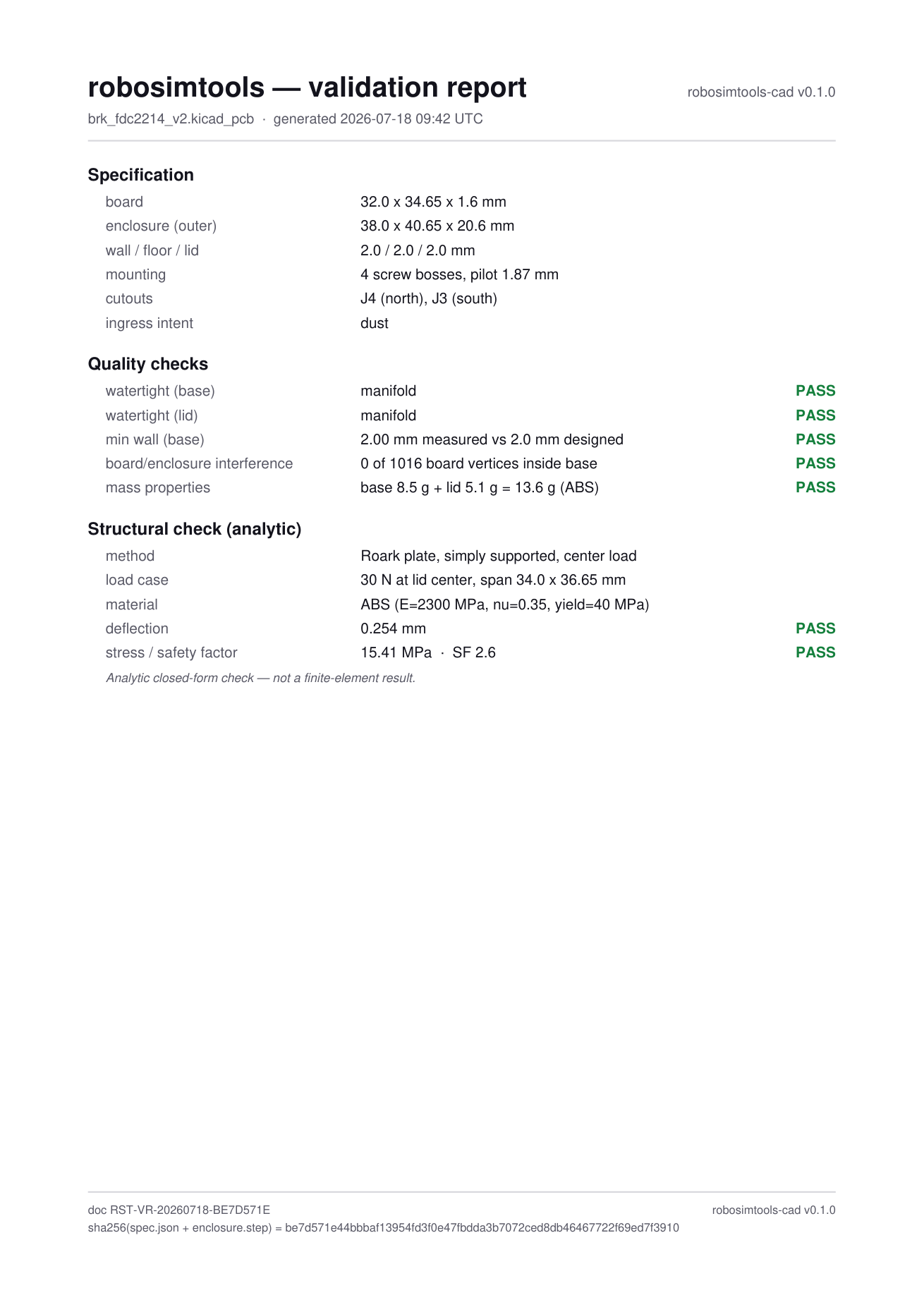
Today the structural check is a fast closed-form analytic calculation (Roark plate model), labelled as such in the report. Basic FEA (finite-element analysis) is coming to CAD Studio — the analytic check ships first because it's instant and traceable; FEA follows for the loads and geometries that need a mesh.
Download this run's actual output: enclosure.step · enclosure.stl · lid.dxf · report.pdf · qc.json · spec.json
One studio, many parts — starting with enclosures.
The same board-aware pipeline extends to the rest of what you keep hand-modelling — plus deeper validation. On the roadmap:
mountsbracketspanel cutoutstest jigsbasic FEA
Where it stands, honestly: the enclosure pipeline is a working prototype and runs today — parsing, CAD generation, QC, and the signed report are real code, not a mock-up. What's in development is the hosted product around it: upload, the plain-language agent, processing, and delivery. Nothing on this page is a screenshot of things that don't exist.
FAQ
What inputs are supported?
KiCad .kicad_pcb at launch (the demo runs on KiCad 10 format). STEP board import is planned — tell us on the waitlist what you’d use.
Is it real geometry or an AI picture?
Real, manufacturable CAD — a parametric solid model (CadQuery/OpenCascade under the hood) exported as STEP/STL/DXF. Everything in the demo video is actual pipeline output, and you can download this run’s files above.
What does "validated" mean?
Every part passes automated checks before you see it: watertightness, minimum wall thickness, board-fit interference, mass properties, and an analytic structural check — summarized in a signed PDF report with a traceable hash.
Only enclosures?
Enclosures are capability #1 because they’re the most common ask. The board-aware core (outline, connectors, holes, heights) is part-agnostic — mounts, brackets, panel cutouts, and test jigs are the roadmap, in waitlist-vote order.
When does it launch?
Soon. Waitlist members hear first, and the first 50 get a free validation report.